Another winter came and spoilt my opportunities to build the car in my own garage. Luckily, I found little room in my relative's garage.
The stand for the water pump is shown in picture 12. It also contains some alternator fasteners.

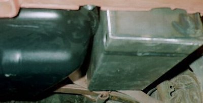
There was no longer room at the engine compartment for the battery. A case for the battery and the fuel pump was manufactured and it was located on the bottom of the trunk. This affects also on the center of gravity positive way. The case is shown in pictures 13a and 13b.

The electrical system of the car was tested. Surprisingly, it worked very well. However, some minor modifications were made. For example, the system was equipped with a main switch that can be operated also during driving if something strange happens.

Because of the modifications of the dashboard, there was no room for the heater controls. The heating system will have a homemade electronic control unit and servos. The solution requires only a small led-panel with push buttons. A quite similar system is found from Regata 100S, though this system might be equipped with a basic microprocessor control. The block diagram is found here. I will publish the schematics when I get the system ready.
The intake and exhaust manifolds are manufactured using mild steel tubing. Its inner diameter is 35mm (1.4") and wall thickness 1.5mm (0.06"). The thickness may not be adequate for the exhaust, but let's try with this... The manifolds are presented in the picture 15. Since there is very limited space, the studs had to be shortened by a few mm to get the manifolds in place! The nuts can be opened only using a slim-design tool.
I tried to make the passages of the intake manifold as similar as possible. A special flange with tapered holes was made to fit the 40mm carburetors to 35mm ID tubes. The end of the tube was also broadened slightly. A few support brackets for the manifold was made, too.
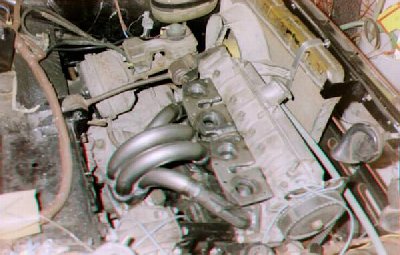
The engine after fitting of the carbs is shown in picture 16. The turbo is also visible. Some kind of a protective shield must be fabricated to protect the steering gear and the alternator from heat.

The next step was to work on the interior. A floor mat that was found from the Ritmo was fitted in the car. The interior is shown in the picture 17a. The picture 17b presents also the main power cords with their shield, the fuel supply line and the hoses for the meters. The back of the dashboard was filled with damping material to reduce the noise level in the cabin.


The trunk was coated using some black hairy mat. The mat was found - surprise - from the Ritmo as well as the wheel box covers. The covers were modified slightly using hot air.

The wires near the steering column were enclosed using 127's original plastic shield. Fortunately, it could be screwed directly to the Ritmo's switch unit. The underside of the dashboard was covered using black plastic plate. The steering column is shown in picture 19. Note the elegant gauges for boost and oil pressure.

