Distributor of a normally aspirated engine is unsuitable for use with turbo because it cannot retard the ignition timing under positive intake manifold pressure. Efficiency of an engine increases with boost pressure and the needed ignition advance gets smaller. In OE turbo ignition units, the boost retardation graph is relatively coarse, virtually 'lowering' the whole ignition advance graph (see the picture 1).
It is nearly impossible to calculate exact values of ignition advance needed, because it depends - among other things - on boost pressure, air/fuel ratio, the shape of combustion chamber, fuel quality and so on. The needed retard rate is approximately 20...28 degrees per bar.
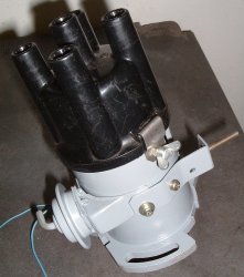
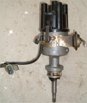
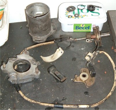
ModificationsThe engine used originally Fiat 128 distributor but it appeared difficult to modify because it did not have a vacuum advance unit at all. A suitable distributor was found from '86 Fiat Regata 70. The distributor of this example is Magneti Marelli s178ex, but the construction is quite similar on different distributors.
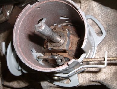
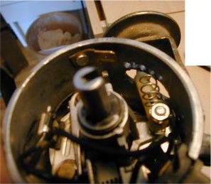
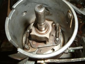
The first task was to dismantle and clean the unit. Almost all of the distributor failures are caused by dirt and sticking.
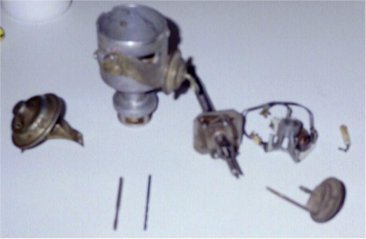
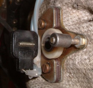
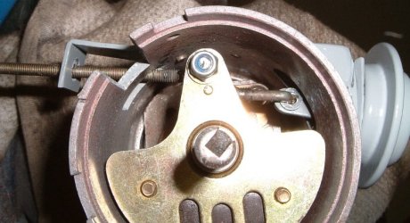
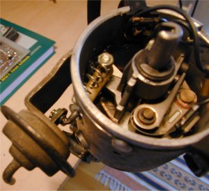
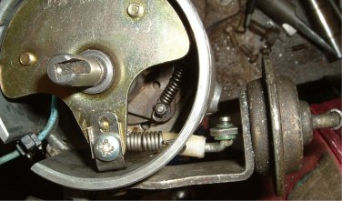
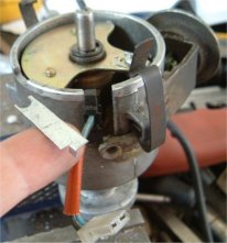
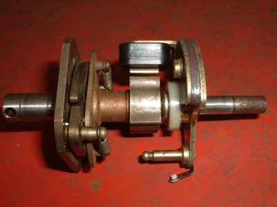
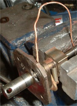
The original vacuum actuator (Pict 3, item 3) is attached to the unit with two screws and its operating arm is simply press-fit on a knob on a turning bottom plate. The vacuum unit of an old distributor is nearly always punctured so I decided to use a diaphragm unit of a vacuum-controlled carburettor. I tested that it can cope with 1 bar maximum pressure. This kind of an actuator has an additional advantage, the spring inside the actuator (1) is usually lighter than one in the original unit. The spring operates in wrong way to our purposes, so it's effect must be as small as possible. This is because we apply positive pressure to the unit, not vacuum. Reverse operation of the timing control is achieved by applying an external return spring (2) between the distributor bottom plate and chassis. The basic principle is shown in picture 3.
The modifications were carried out with quite minimal labor. The knob of the operating arm was drilled away from the bottom plate and replaced with a 25mm long M4 screw. This makes the fitting of a new operating arm and return spring possible. A few holes were drilled to the distributor chassis near the actuator arm hole for the spring. The new actuator and the return spring were attached to the unit. After that, the distributor became ready for testing.
Finding of a suitable spring was quite difficult. With the recent spring, I measured the following retard graph. The retard rate is approx. double compared to the deeded, so I have to find a harder spring or make a bleeder to the actuator hose. The most important thing is that the bottom plate does not stick and the retard rate is quite linear.

I tried a new spring and after that, the following retard graph was found. It is not very linear but quite acceptable. It seems to be difficult to have a linear movement if the spring is very hard and short.
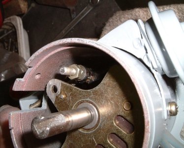
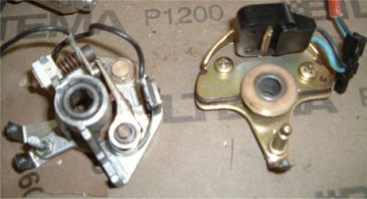
Due to the problems with bouncing breaker points and poor spark performance at high RPM, I decided to switch into a breakerless ignition system. A suitable one was found from newer Fiat Ritmo, actually the distributor is, except for being breakerless, very similar to the one I am using now. However, it is taller so it did not fit into the car's engine compartment. I had to change the components associated with the breakerless system into the old distributor.
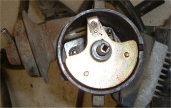
The changed parts include: upper part of the shaft that contains the trigger wheel and base plate with the sender and centrifugal weights. As with the previous one, the base plate needed to be modified in order to accept the boost retard actuator.
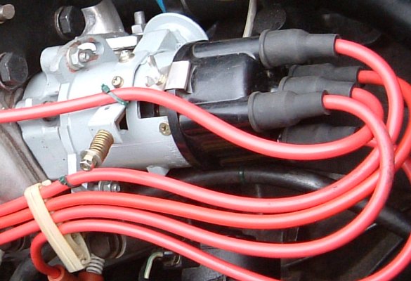
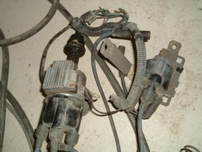
The Ritmo ignition featured the ignition coil amplifier as a part of the distributor. The unit was moved onto the side of the engine compartment, where it cools down more easily.
Because of the re-located ignition amplifier, the ignition sender wiring needed to be modified. The amplifier is now easy to change, for example when one with a rev limiter is needed.

The recent distributor seems to be operating well, but it has some drawbacks - it gives inadequate amount of spark advance during light load conditions (off-boost). The centrifugal advance is only 18 degrees. The total advance will be 28 degrees when taken the 10 degrees base advance into account. This would be ok for an unmodified engine, but this one has some modifications done which decrease its efficiency at low RPM - low compression ratio and fuel delivery optimized for high boost. The too late ignition timing leads to poor fuel economy.
The ignition is also too much retarded at the positive intake manifold pressures. For example, with 10 degrees of boost retard, the total advance will be only 18 degrees at high RPM. This is 10 degrees less than the typical setting for this type of an engine. The engine seems to be more powerful with the boost retard feature disconnected, but then there is a risk of detonation under boost. However, it seems that the total advance would be quite ok for boost situation, even with the maximum centrifugal advance described before, if the base advance is reduced a little. The off-boost situation could then be handled with vacuum advance, like in factory setups.
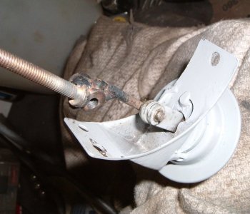
Because of the very limited space at the lower part of the engine compartment, the distributor was decided to locate into the camshaft end. Some newer engines have this type of distributor so there should be no problems with that. This one is from Saab-Lancia 600 - the car had Fiat 1.5 litre engine. However, a drive slot must be machined into the camshaft end. There are no other differences between the engines when talking about cams and camboxes.
It was decided to equip the distributor with similar vacuum actuator like the earlier one described above. The spring is external, that allows to adjust the vacuum advance just by changing different springs.