Building the engine
The following text presents the turbo engine I have built for my 127.
See part 13 for legal requirements of fitting this engine to the Fiat 127.
The engine used is from the Ritmo (also known as Strada). It gives 75bhp in its standard form. Almost similar engine with 10bhp higher power output is found from Regata and Ritmo, too. The engine is from the same series of engines that is used on Uno (55...Turbo ie), 128 and x1/9 models. Its specifications are listed below.
Type: 138A2.000Specifications of the turbo engine (these will be updated later):
Displacement: 1519.5ccPicture 1a presents the block diagram of the engine and its accessories. The components are named below.

Picture 1b shows the lubrication system of the engine. The system is wet-sump based so far. Thin lines are ¼" hose and the thick ones ½".
Stripping the engine
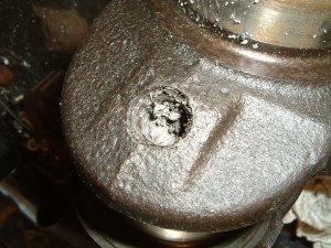
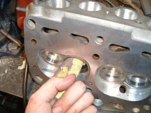
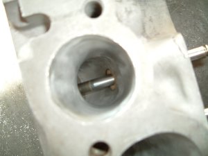
When the engine was stripped, it was noticed to be in quite a good condition. The exhaust port of cylinder 4 appeared to be oily, and the reason for this was found, too. Someone has changed valve oil seals and forgot one of the collets inside the valve springs. Being stupid, he or she had not worried about the missing item and a new one was used. Luckily, no other damages in addition to the oil seal and the collet were found as result.
Bottom-end

The block was bored to 87mm (3.425") to fit Mahle 87mm forged pistons of VW Beetle. Those are cheap since VW engines are very commonly used in motor sports here in Finland. Since the original bore size of the 1498cc engine is 86.4mm (3.402"), displacement was not increased significantly. The bore of the engine cannot be enlarged much singe the cylinders are very close to another.
The compression height of the Mahle pistons was 39.6mm (1.559") and the original ones had only 34.4mm (1.354"). Therefore, when using standard connecting rods and crank, pistons are about 5mm (0.197") proud in the block at TDC. While this is not acceptable, and using of short-stroke crank (of 1116cc or 1290cc engine) did not sound tempting, connecting rods were swapped to shorter 1116cc items. When using those rods, pistons are 3mm (0.118") below the block top surface at TDC. Desired CR of 8.5:1 can be achieved by shaving 1mm (40 thou") from the top of the block. Grooves for the wire rings were machined around the bores. Those are 3.5mm (0.138") wide and 0.7mm (0.028") deep. The rings are manufactured from wire of 2mm x 3.5mm (0.08" x 0.138") and the wire ends are silver-soldered together.
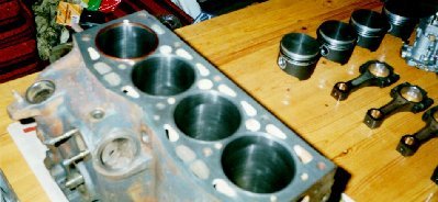

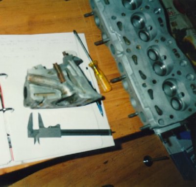
Picture 3a shows the block with the forged pistons and the connecting rods from 1116cc engine. Those are equipped with bushes to accept Mahle pistons with floating pins. Big-end housings were also checked and honed.
Picture 3b shows also Dellorto DRLA40 downdraughts reserved for the engine. These were also used on my 1116cc engine.
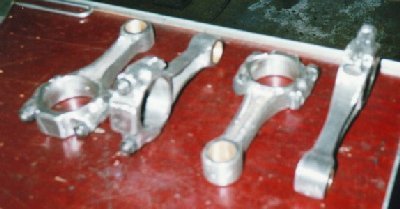
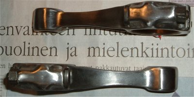
All of the sharp edges of connecting rods were ground off and they were polished. Hopefully this increases their strength. The rods are not lightened significantly. I have heard that the rods of 1499cc engine are forged but the rods of 1116cc engine aren't. Pistons and rods were balanced.


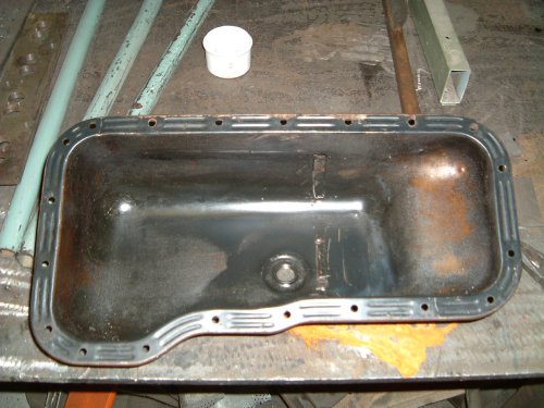
The stock oil sump proved inadequate for anything else than mild road driving. The biggest problem seemed to be that the oil was climbing away from the sump base during hard cornering and the oilpump sucks air. This problem can be solved by making a race sump with trapdoor baffles and full-size windage tray.
The idea of the trapdoor baffles is that the oil can move towards the pump intake but not away from it. This function is achieved using small pieces of metal sheet that can be opened by flowing oil. A solid windage tray is also required to prevent the oil getting over the baffles. The tray also prevents the oil from touching the rotating crankshaft - this can lead to severe bearing damage that is caused by small air bubbles in oil. The similar phenomena is present when the oil sump is overfilled, by the way...
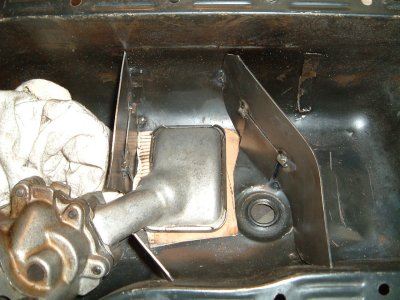
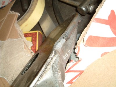
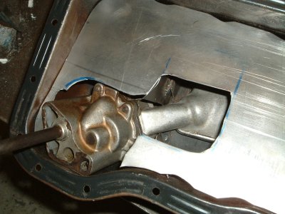
The baffle plates with trapdoors and the windage tray are shown in the pictures below. It was necessary to remove a little piece of metal from the pump intake to ensure that the left trapdoor plate can open freely. The biggest concern with the sump was that oil can quite freely get through the pump intake hole of the baffle. A small plate was made to prevent that - it will be fastened to two oil pump bolts using nuts. The bolts must be replaced to longer items because of that.


Head modifications
The standard head has 36mm (1.417") intake valves and 33mm (1.299") exhausts. Ports are about 28mm (1.102") dia. According to my calculations and literature, satisfactory results could be reached using intake valve size of 39.5mm (1.555"). The standard exhaust valve size can be maintained, but larger one (35mm) would give better results on the pressure charged engine.
The intake valve of desired size can be found from Fiat Tipo/Tempra 1.6 SX and Fiat Punto SX (SOHC). I found also 35.5mm stainless steel exhaust valves from some racing shops. Fortunately, I found valve seats that are not too big and enough clearance between the valve seats can be maintained. At least, 1mm of aluminum should be left to prevent cracking.
The head was ported using a die grinder with carbide burr. With aluminum head, alcohol was used as lubricant to prevent the burr clogging.
Some things must be taken into account when porting the SOHC head. At the section where the port turns (above the valves), the short side and long side turns must remain concentric. Valveguides can be cut in flush with the port roof - especially when very long service life of the valveguides is not expected. However, it is then essential to use bronze guides to prevent cracking. The intake port of STD 1116cc head can be largened to 31mm (be careful!) - 1500 item even more.
Flat profile valves work best with the SOHC head and their shank can be narrowed a little. Three-angle seat cutting improves greatly flow performance especially at low valve lift.
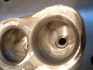
An important modification done to the combustion chamber is straightening the chamber wall near the valves (the wall which contains the spark plug hole). Incoming air-fuel mixture arrives mainly to this area from the intake port, so this is really important job to do. Also, deshrouding the chamber walls near the intake valves improves breathing - especially when larger valves are used. Do not cut the headgasket flamering mating face!


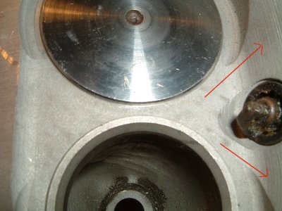
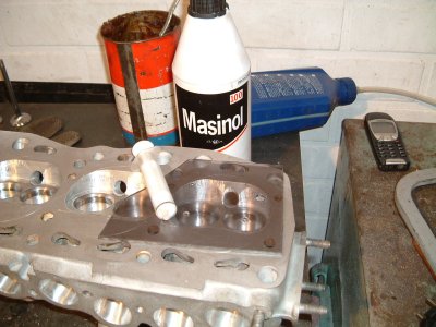
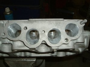
The ports are visible in the picture 4a. At the time of photographing, port ends of the cylinder 1 were largened and the others not, for comparison. Oval-shaped beginning of the intake port was necessity to have enough size. Maximum amount of metal was determined by using a split 1116cc head, which was quite similar to 1498cc one that was under modifications (Picture 5a).
The actual porting job was started after matching the ports into the manifolds. At the first, 1.5mm (0.06") of material was removed from the port sides. When working with only one wall at a time, is quite easy to know how much material needs yet to be removed.
Port height was increased by mainly removing material from the port roof. This helps mixture to turn at the valveguide area, where the port turns down. Head cast is relatively thin near the valveguide, so port height become only 29mm (in) and 27...28mm (ex). Also, guides may become too short is more material is removed.
Port inside and outside turns should be made concentric to prevent turbulence. On the intake side, where the valve seat inner diameter is larger than the port diameter, the port must join smoothly into valve seat area.
Carbide burr leaves relatively rough finish (visible in some pictures). The finishing is carried out using a flapwheel made of small carborundum paper sheets and some finishing paper attached to a small slotted shaft. '80' grade seemed to be OK.

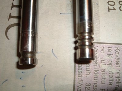
The Punto intake valve was modified and hopefully it now flows better than standard item. The modification was carried out in upright drill, machining the valve using handheld grinders while the valve was rotating.
The stainless steel exhaust valve mentioned above was meant to be used in VW Beetle, but it can be fitted into Fiat head using Ford OHC valve spring fasteners. Fiat double springs will directly fit into Ford items! However, the valve must be shortened by 3mm. After that, there is about 0.8mm difference in valve setup heights which must be compensated, for example, using thicker Volvo shims.


The standard camshaft will be tried, at the first. If very wild camshaft is used in a little turbo engine, the low-end performance of the engine will suffer severely. However, better cam would be one with standard Uno Turbo profile but with more lift.


Fuel system
Fuel is fed to the engine through an electrical high-pressure pump, fuel pressure regulator and two Dellorto carbs. Picture 6 shows the fuel system as diagram.
Special thanks go to my friend Nikola Radenkovic, for valuable information on SOHC heads and tuning.
