Turbo engines always need some kind of control for boost pressure which prevents pressure getting too high and destroying the engine. Some early turbo engines were equipped with simple spring-loaded relief valves on exhaust or intake side. However, much better method is to measure the intake pressure and apply control to the exhaust side.
Picture 1 shows a principal drawing of the wastegate operation. It utilizes an intake-side located actuator that contains a diaphragm. The boost pressure affects the diaphragm and if the pressure gets to high, the actuator opens the exhaust-side bypass valve against spring load. This spring is equipped with an adjustable baseplate that can be used to vary the spring load and the pressure limit where the wastegate is opened.
ComponentsThe bypass valve consists of Fiat TC 36mm exhaust valve, Volvo valveguide and valve body that is made in a lathe from a piece of steel bar. Of course, compatible parts of any vehicle can be used. The body is shown in pictures 2 and 3. A suitable flanges for attaching the unit into exhaust manifold and the actuator are welded in place. After that, it is advisable to use some valve lapping compound to rectify any distortions of the valve mating face, caused by uneven heating during welding.


The actuator is made from old mechanical fuel pump (Fiat 600 item). Lower part of the pump that contains a mechanism for diaphragm movement, is removed using hacksaw. The diaphragm operating bar will be directly connected to the bypass valve. There are also two flap valves in the pump body that must be disabled. One of the two hose joints of the pump can be used as an intake for boost pressure.

The picture 5 shows a cross-sectional drawing of the complete wastegate. In addition to the parts mentioned above, there was also need for 5mm threaded studs, nuts, spring and a sleeve for attacting the actuator arm to the bypass valve. A base plate for the spring was made from a similar steel plate that was welded into the bypass valve body, in order to attach the actuator.
The fuel pump body contains 5 threaded holes for screws that were holding the pump sides together. Those were utilized to attach the actuator to the bypass valve body and the spring baseplate. It is notable that the exhaust and boost pressures must both effect against the spring load. Also, movement of the diaphragm should be on it's normal range.


It is vital that the engine is equipped with a pressure switch that cuts off the ignition or fuel pump if something goes wrong with the boost controls, particularly when trying this kind of homemade things. However, I have experienced no problems with this setup.
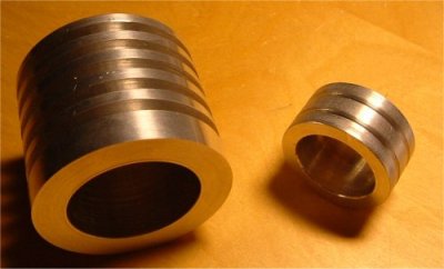
The new billet actuatorTo get easier boost pressure adjustment, a new actuator is being built. It's body is made from aluminum in a lathe, but it will be using the same bypass valve. As seen in the picture 9, the body (1) will be equipped with a cover (2) made from aluminum plate. For that purpose, some threaded holes have to be drilled to the body. The cover also has 3 threaded holes (3) for adjustable spring baseplate (4). The boost pressure intake pipe will be attached to the actuator body (5). The actuator piston (6) contains grooves for O-rings. The picture 8 shows mechanical dimensions of the body and the piston.

Mechanical wastegates have a nasty drawback: They start opening slightly before the maximum boost limit is reached. This causes lower rise rate of the boost pressure because a lot of useful energy is wasted this way. The problem could be cured with an electronic boost controller. While expensive, they offer more accurate operation and this kind of problems do not arise. Of course, this wastegate can be used with electronic control units, too. The boost signal line is equipped with solenoid valve and the wastegate is set to lower pressure limit than the boost limit (controller setting).

The old actuator, made from mechanical fuel pump, was replaced with the new one. However, there has been no problem with the old one. It was noticed that the piston-operated actuator is prone to seize if thermal expansion is not taken into account. The problem was solved by modifying the actuator arm so that it allowed the piston move sidewards. After that, the wastegate was reliable.


