Some background
I have a long time wanted to build my own TC engine - perhaps because of reading the Croft book mentioned on my TC Pages. Nothing too radical - 2l engine, high compression ratio, ported head, race cams and twin carbs - the way it has always been done. I am aiming to 170...180hp power figures.
Base
The engine is from 2l Fiat Croma ie ('87). Its ID is 834B000 which means the non-cat 120hv model. I paid 200 euros for one with blown headgasket - the price includes injection and ignition hardware. Maybe those can be used on some project...
Excluding the headgasket, the engine was in perfect condition. No excessive cylinder wear, good-looking bearings and crankshaft in STD measures... and of course, no cracks in head or block as expected with Fiat/Lancia engine.
Parts?
As told above, Croma block, crank and connecting rods will be used as the bottom end.
Raising CR on 2l TC engines is rather easy - but not very cheap - simply by using 1.6TC pistons. Those come in a few various designs, and some have taller dome than others. For example, Fiat 131/132 pistons have quite small domes while Ritmo/Regata/Strada ones have not less than 8mm high domes. This is the recommended method of raising the CR, because removing too much material from the head can lead to headgasket problems. Also, valve seats are pretty close to the head surface so this makes cutting difficult. However, if a very minor CR rise is wanted, shaving the block may be the answer.
I bought a set of early Regata 100S pistons, 0.4mm oversize. Those have one disadvantage on this engine, cutouts for valves are on wrong sides - machining is needed.

Stock 100S head. Note chamfers for domed pistons - Croma head does not have them.

100S piston.
I decided to save the Croma head for other projects and I chose late model 100S head for this one. This head has small ports and they have very rough finish, especially near the valve pockets - perfect base for my own modifications. The valves are same size as in Croma head (43.5/36) - and in all of the late 8v TC heads I have seen. I believe that the head cast is quite similar with Croma so this one can accept considerably amount of porting.
Cams are from the Regata 100S engine, as well as the camboxes (similar to Croma items). Adjustable cam pulleys seem to be very expensive, luckily I found a CNC-made adjustable center plate that can be married into STD pulley.
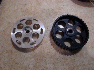
Center plate with STD cam pulley.

Scale
I bought a used pair of Weber 45 DCOE sidedraught carbs. I changed all gaskets and equipped them with initial jetting (tips are found from the Croft book).
Intake manifold proved very difficult to get, because twin carbs are rarely used with the late engines. I noticed that Lancia Beta item will fit (early TC with rearward inclination), because the intake manifold flange of the head is symmetrical. Betas (and their parts) are very rare here, but I found a homemade item - very neatly manufactured, though.
215mm sintered 4-paddle VW Beetle racing item will be used as a clutch disc, with original Sachs pressure plate. However, the disc must be modified to accept Fiat gearbox input shaft.
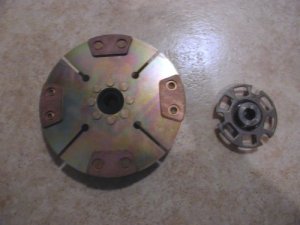
The clutch plate.
I want a lightweight steel flywheel for my engine, but it seems to be extremely difficult to find from anywhere. I made some drawings of this item - hopefully I find a machinist that is competent enough...
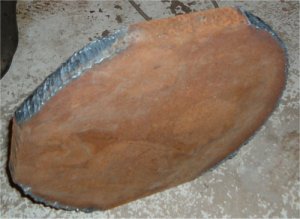
Flywheel billet.
The exhaust manifold will be homemade.
Modifications
I spent a long time wondering which headgasket to use on this engine. 130TC item would be ideal, but I have heard that the early engines have different placement of air holes between the cylinder bores, because the coolant outlet is at the front of the head, unlike in the late models. I had not an opportunity to compare these, though. I ended up using original Croma Turbo item.
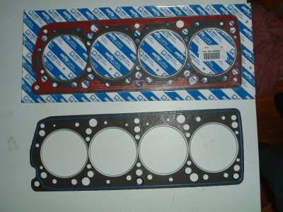
Top: Croma Turbo original, Bottom: Record.
In addition to boring the block to desired oversize, I made a few block modifications. The headgasket contact surface got a few grooves that will accept 1.3mm wire rings made from copper. Unlike the Croma ie, Croma Turbo bottom end has block-mounted oil spray jets that cool pistons. Those have also an additional advance, the oil needed for cylinder lubrication is no more taken from conrod bearings which are highly stressed items. Those conrod holes can be blocked from 'ie' engines simply by using the bearings without holes for the sprays - 16v items. Croma Turbo / 8v Integrale / 1.9 Diesel has this kind of bearings, too, but for some reason their bearing locating lugs are differently placed - the bearing shell looks mirrored.
Croma Turbo / 16v oil jets proved very expensive, but cheaper items are available from Fire engine (Fiat 1.1). Unlike the Croma items, these are directly installed into the main bearing bosses after drilling suitable holes for them.
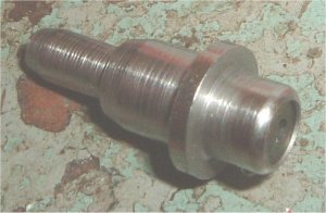
Fire oil jet
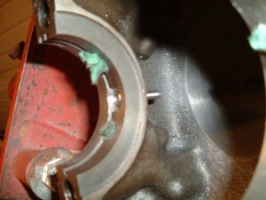
Oil jet in place
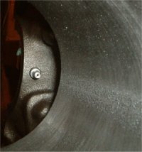
The same as above - top view
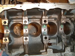
Holes for the oil jets
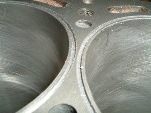
Grooves for the wire rings (1.3mm wide, 1.2mm deep)
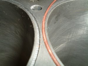
Wire ring fitting
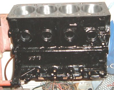
Block finished and painted

Different conrod bearings: Left: Croma ie, middle: 1.9 Diesel / Croma Turbo, right: Lancia 16v. Note the difference between locating lugs.
The Regata pistons I chose have slightly smaller compression height than the Croma items - not good for efficient squish effect between the piston and head. 0.9mm was removed from block surface before cutting the grooves - good squish effect prevents detonation.
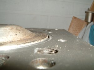
piston at TDC (after shaving the block) - 0.5mm proud in block face.
Crankshaft was modified according to the Croft instructions, and its internal oil passages were cleaned, too.

Main bearing journal modified and lapped. Note the drive for front-located oilpump - distictive for the late model.

Crank
Stock sump is not very good when talking about how well it prevents the oilpump from getting air. Therefore a proper, fully baffled sump was made. Lancia 16v item was used as base (quite similar to Croma item) and the job was started by ripping its standard internals off. The sump contains also some recesses that are needed for Croma crossmember and exhaust, but they can be straightened with this application. The sump was equipped with one-way flapdoors that let the oil flow towards oil pickup only. A wide windage tray was also installed to prevent the oil touching rotating crankshaft. The lubrication system will be equipped with 19-row oil cooler and thermostat.
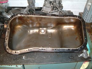
Empty 16v sump. Cambelt shield at left visible - Croma item does not have this.


Sump walls and windage tray
The sump described above become purposeless because the engine was decided to be used on RWD car with a front-mounted engine. That kind of an engine will benefit from wing-type sump. This sump will possibly be used on my Regata... that's another story, though.
Croma head cannot be used with domed pistons without modifications because the missing combustion chamber chamfers (see the text above). The 100S head I am using has them, but without any combustion chamber modifications, the CR climbs too high (over 12:1), especially after shaving the block surface. More chamber volume can be easily achieved by deshrouding the intake valves - this improves intake flow also. In fact, the chamber looks quite much like an early TC chamber after the modifications...
With stock Croma bottom end, use of late 100S head and early 100S piston leads to 11:1 CR.
Intake and exhaust ports were heavily modified. Intake port dia is now about 36mm and it has 34mm venturi. Pistons were also modified a little, mainly because of the too high CR. Piston crown after modification looks more spherical than standard. The resulting CR is 10.9:1 which is OK with race cams. Ports, combustion chambers and piston crowns were polished - ports not too smooth, though...

The head
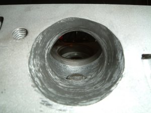
Intake port before finishing
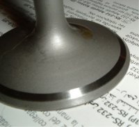
Modified intake valve

Piston crown before polishing
Cams were ground from standard items because the new ones are extremely expensive. Race cams have reduced base circle and this leads to far too wide valve clearances if some material is not removed from the base of the camboxes. Use of thicker Volvo shims did not sound practical because of the additional weight - the desired maximum revs (7300RPM) are already near the limits of the STD valve springs. 1.5mm was shaved from both boxes. The cam duration is 304 degrees and maximum lift 10.5 mm.
Building up
I started with the cylinder head because all of the parts were available. Camshaft and cambox are at first bolted in place using old gasket, to find out the needed shim thicknesses. However, it may be necessary to change some shims afterwards. Suitable tool for pressing the valve buckets can be made from wide chisel-type screwdriver simply by bending it 90 degrees.
Ready built head must be handled with care, valves can easily bend because a few valves always protrude from the head face when cams are in place. When turning cams and measuring the valve clearances without cambelt, it would be wise to keep only one camshaft in place at once.

Head built ready, still without valve covers. Note the brackets under the head - they prevent the valves from bending.

Camshaft lobe, shim and bucket.
Update 06.03.03:
I finally got the steel flywheel and the starter ring gear was installed using an oven. The wheel weighs 4.8kg (10.5lbs) which is a significant improvement over the stock item (more than 8kg/17.6lbs).

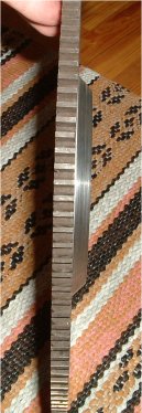
The new steel flywheel with the Croma ring gear.
I found out that more durable 1" wide Regata 1.7D cambelt can be used to replace the standard 3/4" item. The belt is one tooth shorter than the Croma belt but this is not a problem because I have removed almost 1mm from the block top surface. However, the crank nose pulley should be modified for this, because it is too narrow... the old vertical-type engines accept the 1" belt without problems.

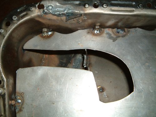
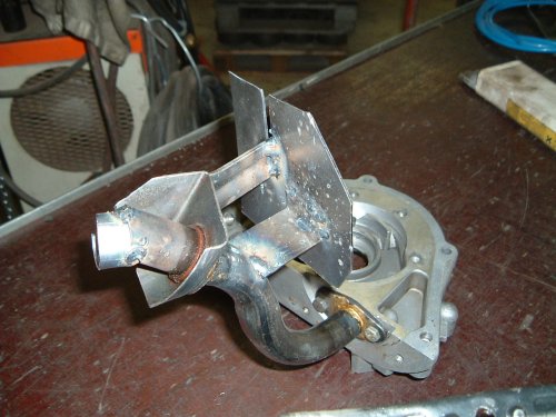
Sump modifications.
I made a few modifications to the sump, the windage tray can now be bolted in place prior installing the sump into the engine. The oil pump intake pipe also got some external baffle plates that block some holes from the windage tray.
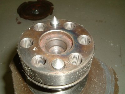
6.2.2004:Back in business! After balancing the crank assembly, it is time to put the parts together... I installed the oil jets using Locktite sealant. Flywheel needs two holes for the dowels to be drilled, the cones made for marking are visible in the picture belown (needed some shortening).

10.2.2004:
Since the engine has been apart before, it was advisable to check bearing clearances. This is quite easily done using a piece Plastigage-strip that is left inside the bearing when the bearing cap bolts are torqued to given setting. The clearance can then be estimated how much the strip is flattened.


The oil filter bracket of the 1.6 litre engine is much simplier and weighs a lot less than Croma 2l counterpart. It was chosen to be used on this engine. That was the case also with crankshaft V-belt pulleys. Care must be taken when installing the 1.6 oil filter bracket gasket, it can be also put in wrong way around and it will then block the oil feed gallery!
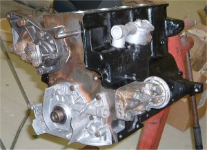

Croma oil pump is slightly different compared to the 1.6 item.. that's why some external mods had to be carried out to make the pulley fit.
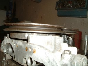
19.2.2004:
I decided to have the cams nitrided. This greatly increases their durability. So I had to take the head apart again...
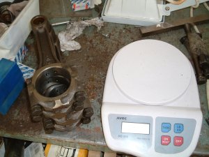
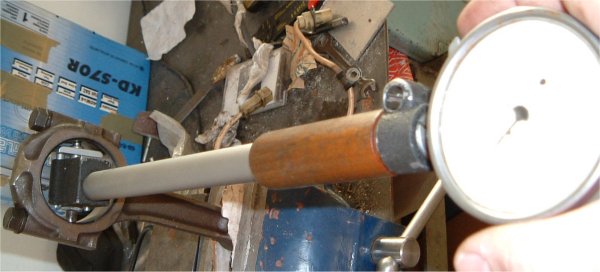
The connecting rods were weight-matched and balanced, and the bearing bores were checked for ovality. The bores were near their upper limits, but ok. More alarming thing is that the conrod bolts seem to center the cap very poorly - the phenomenon I have seen also in other late TCs with bolt-fixed rod caps! This could possibly be cured by machining the sides of the rod straight when the rod is tightened that way the bores are round (measured with the inside micrometer or bore gauge). When putting the rods in place, the centering could be then done by looking at the rod sides (hard to explain with my English skills). Unfortunately I found this idea afterwards..
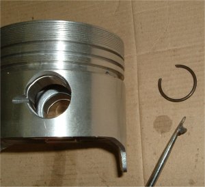
I was not having fun when fitting the strong circlips to the new pistons. The clip groove was located deeper in the piston pin bore compared to the situation with standard 2l items - possibly the different manufacturer was the cause. I modified an old screwdriver to do the job. It is easy to understand why there is a factory tool for that - a tapered piece of tube with a special press. The piston rings were perfectly suitable as-is and using a file was unnecessary.

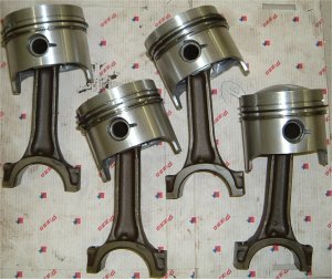
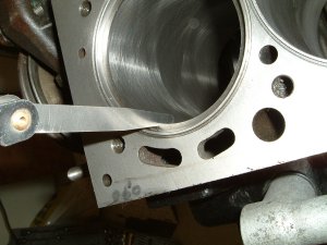
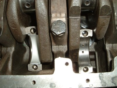
The next task was to put the pistons in - the turbo/diesel bearings are also visible in the pictures below. They block the spray holes from the connecting rods because separate oil jets are used. The bearing clearances were a bit on high side, but nothing dangerous.
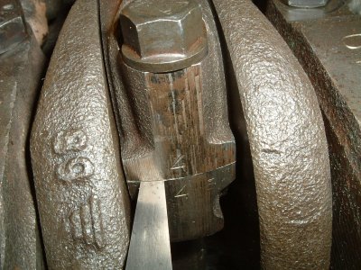
It is vital to check the bearing tightness to their bores. This is done by undoing one bolt when the other one is torqued - the bearing cap should rise about 0.2 mm from its mating surface.

17.3.2004:
I made an oil pump intake from an old oil filter case.. the gauze is soldered in place, because welding produces hard metal debris that can enter the intake pipe and the oilpump, leading to pump failure.
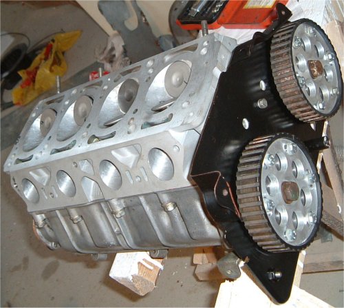
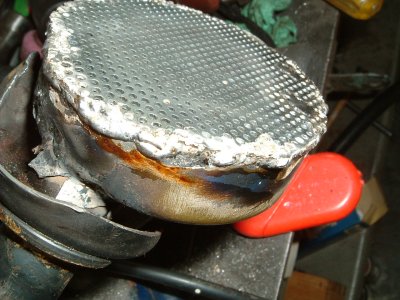
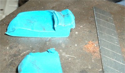
The head was put together after the cams were nitrided. Before that, light polishing with fine-grade carborundum paper was necessary. The cams were timed according to the manufacturer's recommendations - Intake 3mm open @ TDC and exhaust 2.6mm @ TDC. Then the valve-piston clearances were measured using pieces of Plasticine placed on the top of the pistons - the minimum clearance was 3mm on exhaust and 4mm on intake side. It would be nice to have some more margin for timing adjustments...
It is vital to pre-lubricate the camshafts with graphite or MoS grease before installation.
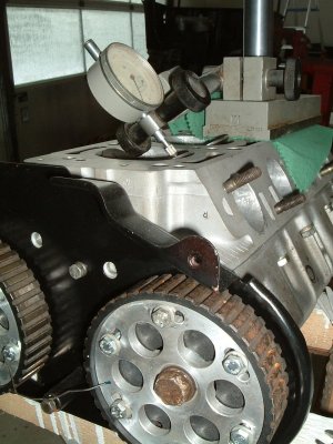
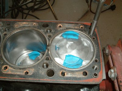
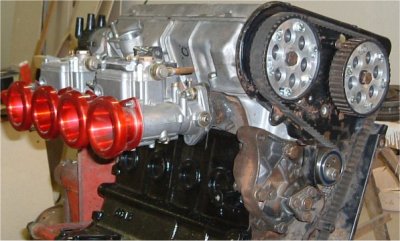
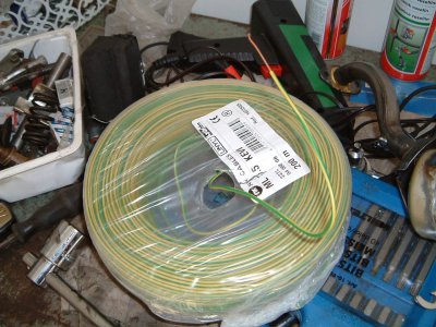
At this time, fitment of the intake manifold and carbs were checked. The copper wire rings (and the material for them) are also visible in the pictures below.
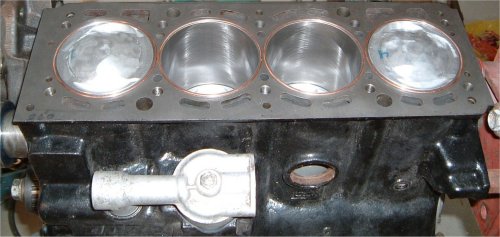
26.3.2004:
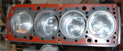
The oil passage that is most prone to leak was reinforced with an o-ring. During installation of the head gasket, it is vital to check that all of the six oil feed channel holes (in the picture below, pointed with arrows) are present, some 8v gasket sets have had a 16v type head gasket with only 2 front passages - using this unmodified leads to camshaft failure.
Before installation, the gasket was coated with VHT Copper Gasket Cement. The head was put in place with a new set of head bolts. Note the use of two old head bolt stems that guide the head in place. Remember to install both of the head gasket locating dowels!
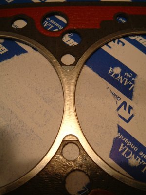
In one of the pictures below, the reinforcement between the cylinders is shown. Only OE gaskets have this, so the cheap replacement gaskets won't last long in the TC-engine with the bores close to another.

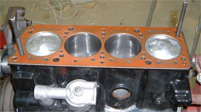
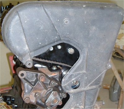
The head in place is shown in the pictures below, as well as the Croma cambelt cover. This cover has a distinctive recess for the engine support bar while the 100S item doesn't. The covers are not interchangeable - they have different dimensions, and their fasteners are also located differently.

