Background
My Telma is of type AC61-35 (or I think so, because there were no markings left...) that equals to type CC135. This brake can handle maximum 650 horsepower with the maximum RPM rating of 4000. The maximum braking torque is 1350 Nm. The unit weighs about 230 kg. Some information can be behind from the links at the bottom of this page.
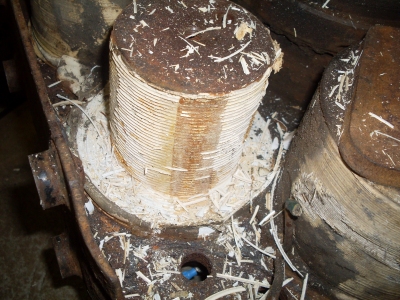
Despite of its appearance, the retarder seemed to be in moderate condition. The rotors and stators were rusty but the bearings were intact. The spacer ring shown in the pictures below was missing from one side, so a new one must be made.


The retarder before reconditioning, the bearing runner mentioned in context, and the unit with the rotors dismantled.
Restoration
After some investigations, I decided to strip down all the wirings of the retarder. They differ much from all the schematics found from manuals - this unit seems to be some custom-made version. In addition, the wires and connection blocks are very corroded and look dodgy. I am also planning to re-arrange the coil connections, so I can use higher voltage for exciting - the current needed will be lower then. The brake will need over 3 kW of electrical power at full braking capacity, so the currents needed will be very large, if low voltage is used for exciting. The original circuitry is often built for 24V or even 12V, depending on the model.
At least partial dismantling of wiring is also necessary to check and measure the condition of the coils.


Corroded wirings before dismantling.
Condition of the windings was tested with multimeter and battery charger. Some of the coils worked well but over half of the 16 coils had broken wires. Aluminum wire is not very resistant against corrosion. Since the spare parts are almost unavailable,the only option is to fix the windings.
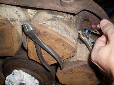
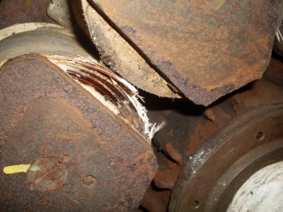
A working coil with a pair of pliers and corroded windings of another coil.
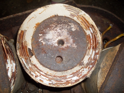
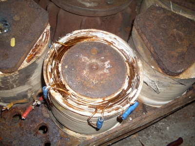
Pole shoes needed to come off, for repairing the windings.
Some of the coil windings were still repairable. However, reliability of this kind of repair is questionable because there will be extra junctions. They must be done by crimping because the aluminium is not solderable. However, the coils must be at least re-tested with the maximum current before putting the parts of the dyno bench together.
Four coils were not possible to repair in place. The windings were uncoiled and a new, replacing coils must be manufactured. I have ordered new, 2,36 mm diameter wire for this. As the aluminum wire is quite hard to find in small amounts, I will have some excess.

A pole without winding. All the rust was removed from the retarder frame and new paint was applied.
