Background
While building my new garage, I decided to start a project that covers both of my hobbies - cars and electronics. I have a long time been thinking of having by own power dyno, and a device based on an eddy-current brake sounded the best alternative. In addition, most of the best power dynos come with this type of brake. It has no wearing parts in addition to the bearings, it does not need any coolant and the braking force is easy to control.
There are some links at the bottom of this page that I have found useful.
The retarder
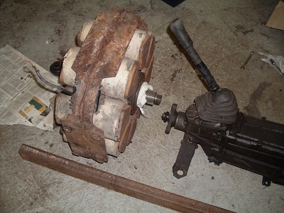
After a long seeking, I purchased an old eddy-current brake, also called as a retarder. This Telma is from a bus. Those retarders are common on the newish buses only, hence their availability was very limited for a hobbyist with a limited budget. Also, older vehicles equipped with automatic or semi-automatic transmission can have this type of a retarder.
The story about the details and restoration of the retarder can now be found from here.Dyno bench structure
At the first, I was thinking of using one retarder for braking and an automotive gearbox as a reduction gear. It will reduce the retarder speed to 4000 RPM maximum, that is the highest RPM limit for the retarders. However, the plans changed during the project...

The original idea about the layout.
A crude drawing below shows the new structure of the dyno bench I am designing and building. Differing from my previous plans, I will be using two retarders and a reduction gear between them. Now, it is possible to use a rear axle from an ordinary RWD car as a reduction gear - very easy to obtain.
Read more about the transmission here.The retarders and the transmission are mounted into an inner frame, that is hung to the outer (main) frame with a pair of bearings. The inner frame would be free to rotate if it was not held in place with an arm that is connected to the load cell. This measures the twisting force of the inner frame, and the engine torque can be calculated from this. The engine under test is mounted to the outer frame.
Structure like this offers a significant advantage - the inner frame is naturally balanced so the load cell carries no force when there is no brake force applied, thus no need for additional balancing. In addition, the losses caused by the transmission are included in the force measured by the load cell - no need for complex and inaccurate approximation for the transmission loss.
A basic diagram of the engine dyno bench.
An another retarder was obviously needed. I found a couple of more of them from a scrap yard (near Lahti city) I discovered by means of a tip from Internet discussions.
The story about the second retarder can be found from here.Obviously the power capacity of the dyno doubled, which is not a bad thing.
